In the first experiment, we will use truth tables computed by the Digital tool to
validate the three equivalences stated in (2.1), (2.2), and (2.3).
Tasks
Use the Digital tool to draw each of the three original circuits Fig. 2.1.1
Fig. 2.1.1 NOT-NOT (left), NAND (middle), and NOR (right) circuit.
and the three corresponding transformed circuits in Fig. 2.1.2
Fig. 2.1.2 Transformed NOT-NOT (left), NAND (middle), and NOR (right) circuit.
representing the left- and right-hand sides
of the equations (2.1), (2.2), and (2.3), respectively.
Hint
You need to add labeled inputs and outputs to the circuits.
Use the analyze option (F9, Analyse/Analyse) from the Digital tool to derive the truth table for each circuit.
Compare the resulting truth tables for each circuit pair and validate their equivalence, i.e.,
check that the original and transformed circuits produce the same outputs.
Save and submit the circuits (as {NOT-NOT,NAND,NOR}_{orig,trans}.dig e.g., NOT-NOT_orig.dig and NOT-NOT_trans.dig)
and the truth tables in corresponding csv-files (as NOT-NOT_orig.csv and NOT-NOT_trans.csv).
The bubble pushing algorithm is a method to transform a combinational circuit
that uses NAND, NOR, and NOT gates into an equivalent circuit that only uses AND, OR, and NOT gates.
The algorithm can be described by the following set of rules:
Begin at the output of the circuit and work toward the inputs
Push any bubbles on the final output back toward the inputs
Draw each gate so that bubbles cancel
Use the bubble pushing algorithm for the circuit shown in Fig. 2.2.1.
Derive (by hand) an equivalent circuit for the circuit depicted
in Fig. 2.2.1 that only uses AND, OR, and NOT gates.
Draw the original and transformed circuit in the Digital tool and derive their corresponding truth tables.
Use the truth tables to validate the equivalence of both circuits, i.e.,
check that the original and transformed circuit produce the same outputs.
Save and submit the equivalent boolean equation in SOP (as bubble1.txt) besides its circuit (as bubble1.dig) and truth table (in csv-format as bubble1.csv).
Derive the equivalent boolean equation (in SOP) for the circuit in Fig. 2.3.1.
Draw the transformed circuit in the Digital tool and derive the corresponding truth tables.
Use the truth tables to validate the equivalence of both circuits.
Save and submit the equivalent boolean equation in SOP (as bubble2.txt) besides its circuit (as bubble2.dig) and truth table (in csv-format as bubble2.csv).
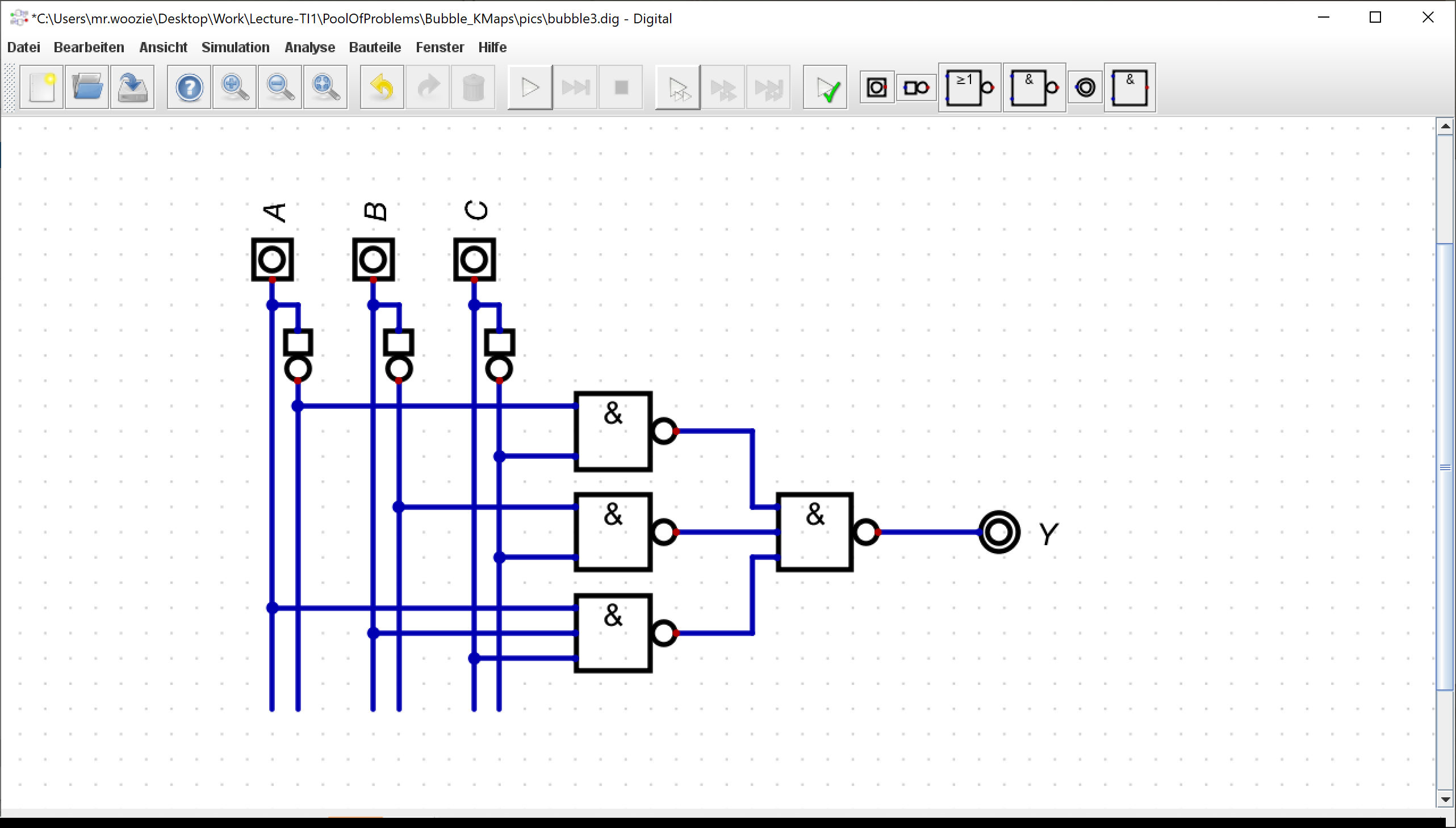
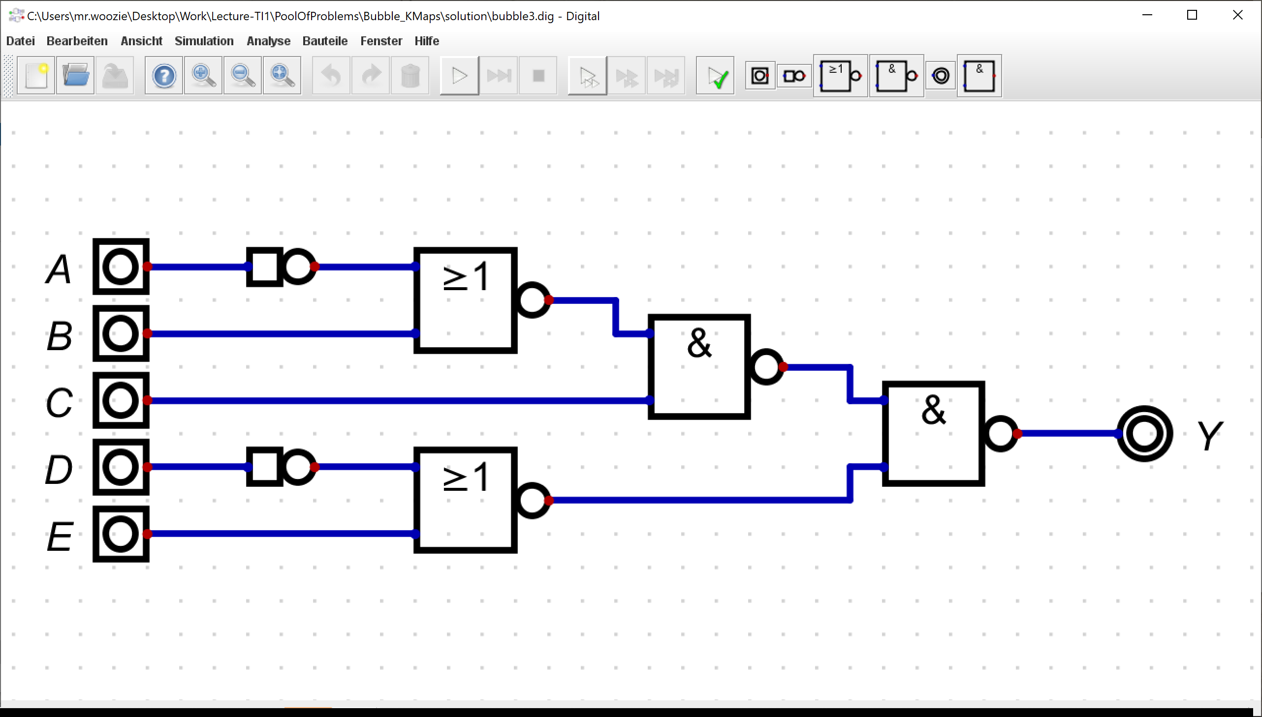
Derive the equivalent boolean equation (in SOP) for the circuit in Fig. 2.4.1.
Draw the transformed circuit in the Digital tool and derive the corresponding truth tables.
Use the truth tables to validate the equivalence of both circuits.
Save and submit the equivalent boolean equation in SOP (as bubble3.txt) besides its circuit (as bubble3.dig) and truth table (in csv-format as bubble3.csv).