4. Finite State Machines
4.1. Simple Coffee Vending Machine
In this experiment, we will develop a finite state machine (FSM) for a simple coffee vending machine. The machine provides a cup of freshly brewed coffee for 1 Euro. If a coin is inserted into the machine (we assume that only 1 Euro coins fit in the slot), the user can press a button to order the drink. Of course, if no money is provided, our machine should also not provide a drink. Also, since we are a greedy company, we do accept more coins but do not provide more than one coffee if the user has overpaid.
Current State |
Input |
Next State |
Output |
|---|---|---|---|
waiting for payment |
coin |
payment received |
Switch light on informing user to press the button |
press |
waiting for payment |
None |
|
payment received |
coin |
payment received |
None |
press |
waiting for payment |
Brew a delicious coffee and go back to original mode |
Tasks
Verify that Fig. 4.1.1 represents the state transition diagram

Fig. 4.1.1 State transition diagram for the coffee vending machine.
for the FSM described in Table 4.1.1.
Convince yourself that the abstract Mealy formulation in Table 4.1.2 with the following states
S0 for the state
waiting for paymentS1 for the state
payment received
using the inputs
A for the input
coin insertedB for the input
Button B pressed (coffee)
and outputs
Y1 for light on/off
Y2 for brew one/no coffee
satisfies our goals.
Table 4.1.2 Mealy state transition table with outputs for the simple coffee machine. Current
Input
Next State
Output
State

A
B

Y1
Y2
0
1
X
1
0
0
0
0
X
0
0
0
1
X
0
1
1
0
1
X
1
0
1
1
NOTE: Any additional coin will be lost in the overpayment scenario if the user inserts money while pressing the button.
Verify the correctness of the boolean equations for the next state and the outputs in sum-of-product form
(4.1.1)

Draw the following circuit using the Digital tool and check that it produces the correct outputs.
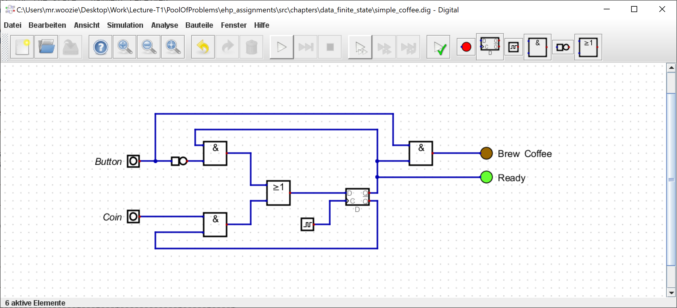
Fig. 4.1.2 Circuit for the simple coffee machine.
Hint
You will find the clock in the menu (Bauteile/IO/Takteingang). It can be activated by right-clicking on it and checking the
Echtzeittakt startenbox. Also, you might want to use a release button (Bauteile/IO/Taster) for the inputs. Note that you might observe unexpected behaviour depending on how long you press the button.
4.2. Fair Coffee Vending Machine
Due to a large number of customer complaints, it was decided to change the overpayment policy and develop a finite state machine for a more fair coffee vending machine. As before, the machine has a slot that only accepts 1 Euro coins. However, the machine will now accept up to two coins before ordering a coffee and will return any excessive amount of coins. After inserting money, the user will have the option to order a small (1 Euro) or a LARGE coffee (2 Euro) by pressing the corresponding buttons B1 or B2, respectively.
The state transition table for the fair coffee machine is given in Table 4.2.1.
Current State |
Input |
Next State |
Output |
|---|---|---|---|
waiting for payment |
coin |
payment received |
Switch on light to indicate that machine is ready to brew |
B1 |
waiting for payment |
None |
|
B2 |
waiting for payment |
None |
|
payment received |
coin |
overpayment received |
Keep light on |
B1 |
waiting for payment |
Brew a small coffee and switch off light |
|
B2 |
payment received |
None |
|
overpayment received |
coin |
overpayment received |
Return one coin |
B1 |
payment recived |
Brew a small coffee |
|
B2 |
waiting for payment |
Brew a LARGE coffee and switch light off |
Tasks
Draw a state transition diagram for the FSM using the states
S0 for the state
waiting for paymentS1 for the state
payment receivedS2 for the state
overpayment received
using the inputs
A for the input
coin insertedB1 for the input
Button B1 pressed (small coffee)B2 for the input
Button B2 pressed (LARGE coffee)
Formulate the corresponding tables for the state transistion, the binary state encoding, and output encoding.
Write down the boolean equations for the next state and the outputs in sum-of-product form.
Implement the circuit in the Digital tool.
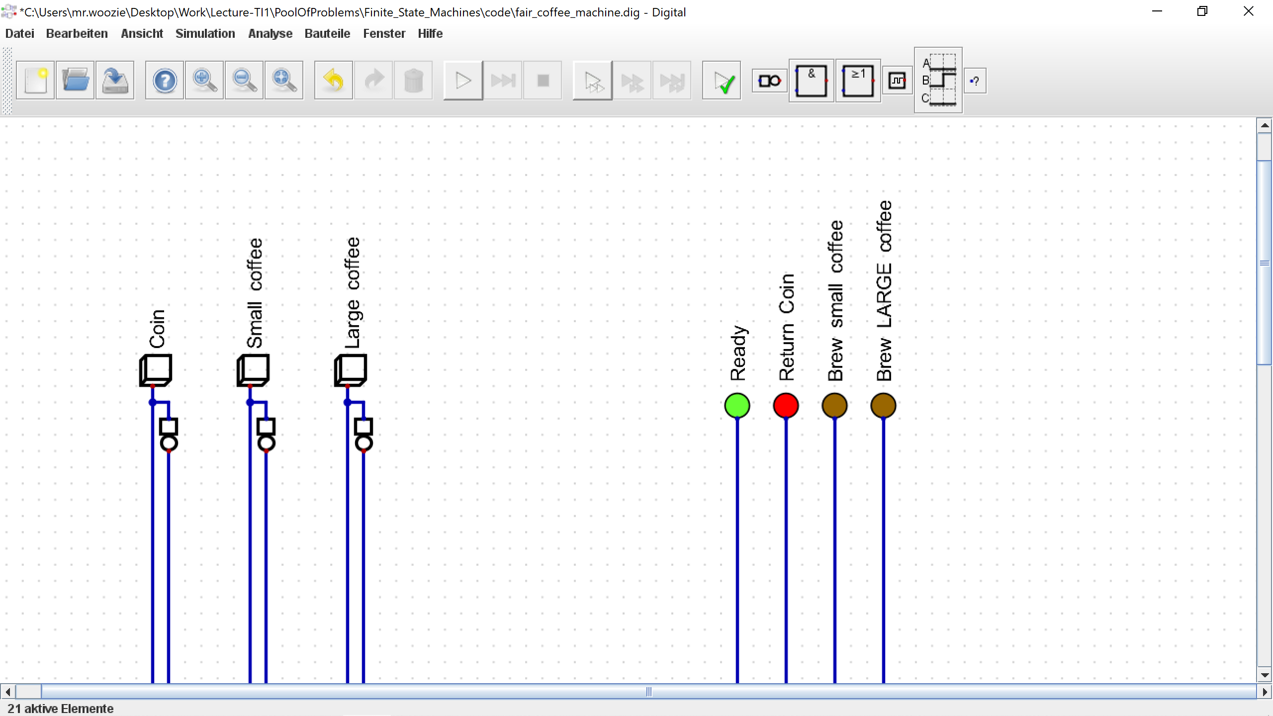
Fig. 4.2.1 Incomplete circuit for the fair coffee machine.
Hint
AND, OR, … logic gates can have more than two inputs. To change the number of inputs, you need to right-click on the gate and set Anzahl der Eingänge to the desired value.
Test your circuit and validate that it produces the correct outputs.
Save and submit the state transition diagram (as
fair_coffee_machine.svg), the tables for the state transistion (asfair_coffee_machine_transition.csv), the binary state encoding (asfair_coffee_machine_encoding.csv), and output encoding (asfair_coffee_machine_output.csv) besides a txt-file with the boolean equations (asfair_coffee_machine.txt) and the circuit (asfair_coffee_machine.dig).
4.3. Fancy Coffee Vending Machine
The fair coffee machine was a big success and most customers are happy. However, there are still some people who would like to enjoy a fancy Latte Macchiato. Thus, the company has decided to also offer this option at a price of 3 Euros and design a new vending machine. The new machine now accepts up to three coins before ordering a coffee and will return any excessive amount of coins. After inserting (sufficient) money, the user will have the option to order a small (1 Euro), a LARGE coffee (2 Euro), or a fancy Latte Macchiato by pressing the corresponding buttons B1, B2, or B3, respectively.
Your task is to extend the state transition table in Table 4.2.1 by appropriate states, inputs and outputs to achieve this goal.
Tasks
Draw a state transition diagram for the FSM of the fancy coffee maschine.
Formulate the corresponding tables for the state transistion, the binary state encoding, and output encoding.
Write down the boolean equations for the next state in sum-of-product form.
Implement the circuit in the Digital tool.
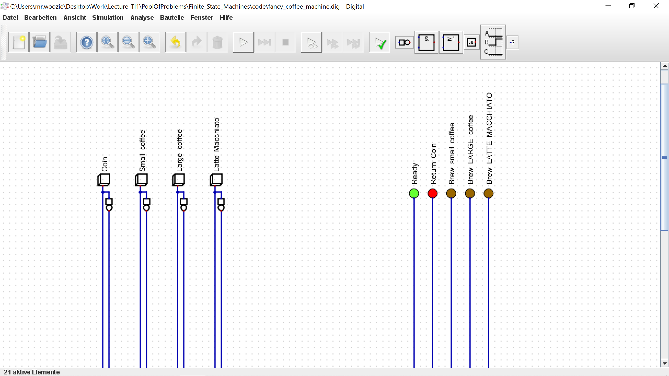
Fig. 4.3.1 Incomplete circuit for the fancy coffee machine.
Test your circuit and validate that it produces the correct outputs.
Save and submit the state transition diagram (as
fancy_coffee_machine.svg), the tables for the state transistion (asfancy_coffee_machine_transition.csv), the binary state encoding (asfancy_coffee_machine_encoding.csv), and output encoding (asfancy_coffee_machine_output.csv) besides besides a txt-file with the boolean equations (asfancy_coffee_machine.txt) and the circuit (asfancy_coffee_machine.dig).